TPS5430 vs TPS5450: Differences and How to Choose
TPS5430 and TPS5450 compared: same 5.5–36 V input, 500 kHz and 8-pin PowerPAD package, but 3 A versus 5 A output. When each fits, and related alternatives.
- Power Management
- DC-DC
- Texas Instruments
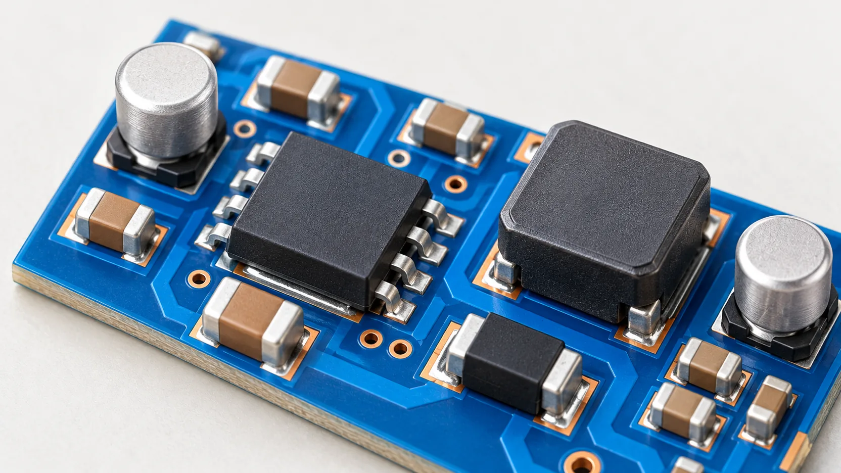
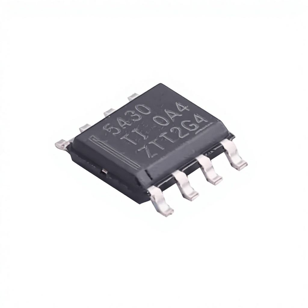
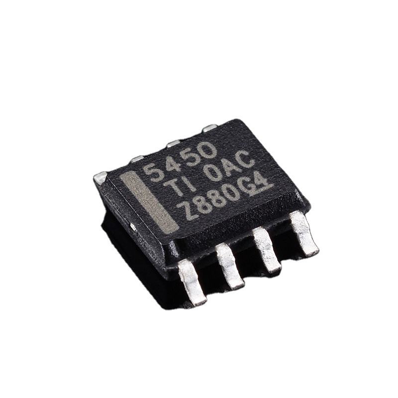
The Texas Instruments TPS5430 and TPS5450 are step-down (buck) converters with an integrated high-side MOSFET, widely used to turn 12 V or 24 V rails into 5 V or 3.3 V in industrial, communication and embedded equipment. They look almost the same on a datasheet summary, so it is worth being clear about what is shared and what is different.
Key Specifications Side by Side
| Parameter | TPS5430DDAR | TPS5450DDAR |
|---|---|---|
| Input voltage | 5.5 V to 36 V | 5.5 V to 36 V |
| Output current (continuous) | 3 A | 5 A |
| Switching frequency | 500 kHz (fixed) | 500 kHz (fixed) |
| Reference / minimum output | 1.221 V | 1.221 V |
| Rectification | Non-synchronous (external diode) | Non-synchronous (external diode) |
| Package | 8-pin SO PowerPAD (DDA) | 8-pin SO PowerPAD (DDA) |
| Junction temperature | -40 °C to 125 °C | -40 °C to 125 °C |
Values are from distributor product data for the DDAR (tape and reel) ordering codes. Confirm details in the TI datasheet for your exact part.
What Is the Same
Both devices use the same 8-pin PowerPAD package and pin arrangement, the same 500 kHz fixed switching frequency and the same 1.221 V reference, and both are non-synchronous converters that need an external catch diode, typically a Schottky. Both include internal compensation, which keeps the external component count low. The exposed thermal pad must be soldered to a copper area on the PCB for either part to reach its rated current.
The Real Difference: Output Current
The TPS5430 is rated for 3 A continuous output and the TPS5450 for 5 A. The TPS5450 also has a higher switch current limit to support that rating. In practice this means the TPS5450 can replace a TPS5430 on the same footprint when a design needs more current, but the rest of the power stage must be checked:
- Inductor: saturation and RMS current ratings must cover the higher load current plus ripple.
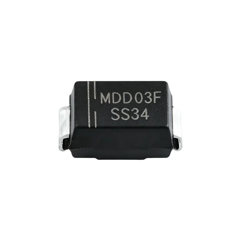
- Catch diode: its average current rating must suit the higher output current; for example the SS34 (3 A) suits many TPS5430 designs, while 5 A designs need a larger diode.
- Input and output capacitors: ripple current ratings rise with load current.
- Thermal design: higher current means more dissipation; review copper area and airflow.
Going the other way, using a TPS5430 in a 5 A design, is not possible: it would hit current limit.
Which One to Choose
Choose the TPS5430 when the load stays at or below 3 A with margin. It is usually the lower-cost part and the external components can be smaller. Choose the TPS5450 when the load needs up to 5 A, or when you want headroom on the same footprint for future variants of a product.
Related Alternatives
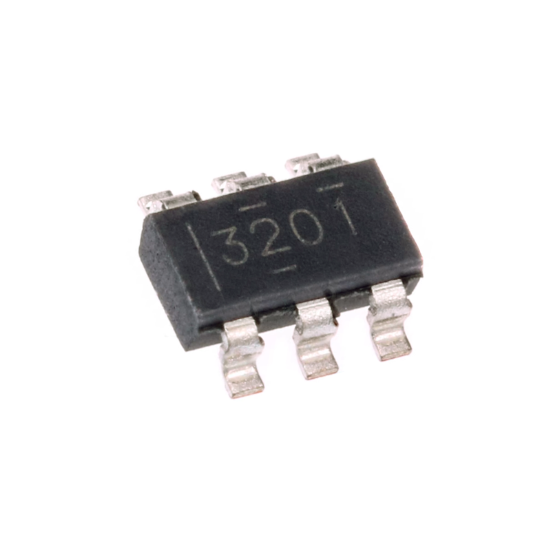
Do not confuse the TPS5430 with the TPS54302: it is a different, synchronous converter for 4.5 V to 28 V input in a SOT-23 package, not a variant of the TPS5430. For lower input voltages, parts such as the TPS54331 (3.5 V to 28 V, 3 A, 570 kHz, 8-SOIC) or the compact TPS563201 are common choices, but neither is pin-compatible with the TPS5430, so they need a new layout.
Summary
The TPS5430 and TPS5450 share input range, frequency, reference and package. The difference is output current: 3 A versus 5 A. The TPS5450 can upgrade a TPS5430 footprint, provided the inductor, diode, capacitors and thermal design are checked for the higher current.
Need either part? Request a quote for the TPS5430 or TPS5450, or send your power-section BOM for review.